Wednesday, February 22, 2012

Advance Design for L3 VPN

Full Mesh:- Achieves full redundancy between all the sites.


Hub and Spoke:- HQ and branch office scenarios


Extranet:- Share resources between the different customer sites or share resources between the customers and the suppliers.


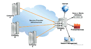
Overlapping:- Typically used to access common resources like Firewalls or other servers


In the case of full mesh every site has a connection to the other sites.


The route distinguisher between the PE and the CE routers should be same and the import and the export route targets should be same.


In this design scalability issues might arise if the number of PE's is substantially large.


Route reflectors in VPRN:-


Here it is not mandatory to have a full mesh of ibgp sessions.


With RR's the PE forms adjacency only with the RR's and not with all the PE's


Classical iBGP split horizon rules mandate that updates
received on eBGP sessions should be forwarded to all iBGP and eBGP sessions, but updates
received on an iBGP session should be forwarded only to all eBGP sessions. This requires the BGP
edge router to send updates to all other BGP-enabled routers in its own AS directly through individual
iBGP sessions to each BGP router.


RRs modify the iBGP split horizon rule and allow a specific router,
under certain conditions, to forward all incoming iBGP updates to an outgoing iBGP session. This
router is called a route-reflector.


In the absence of RRs, whenever a new PE is introduced, every existing PE in the service provider
network will require an additional BGP neighbor command associating it with the new PE. In BGP,
updates received by a peer in an AS are not allowed to be forwarded to another peer within the same
AS. Therefore, a BGP network must be fully meshed, with all peers adjacent to one another, as far as
BGP routing updates are concerned. If the number of PEs becomes substantial enough to make this
operation impractical, BGP RRs are recommended. RRs avert the need to fully mesh the BGP peers
and avoid adding neighbor commands to each PE. With RRs, the PEs would only require neighbors
defined for each RR. Any updates, including VRF information, would be sent to the RR alone. The
RRs are then responsible for propagating information received from PEs to all the other PEs.
RRs are also useful in the event of a route change in the customer network. Without RRs, the PE that
locally terminates the portion of the customer network would have to update every PE peer
participating in that VPN. RRs, therefore, help remove the burden of BGP updates from the PE.


Hub and Spoke:-

The client sites requires direct connection to the HQ office but the client sites does not require connection with each other.
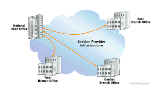


This design offers less redundancy and loss of a router will lead to loss of some services but the benefit is manifold as it reduces cost.


In this case the number of VPN tunnels are reduced, filtering or any policy can only be applied to the hub site.


The downside is spoke sites can only send and receive traffic through the hub site.


Spoke to spoke is possible but it should be passing through the hub site.


The rules that are followed are:-


The policies that are required to implement this topology are outlined
below. Any access not specifically mentioned is not to be permitted.
The hub site PE should learn all of the routes from the spoke sites.
The spoke sites should only learn routes from the hub site.


Given below is what it will happen the export route targets for all the spoke sites will be impoerted by the hub site while the export route target for the hub site will be imported by the spoke sites.


CE Hub and Spoke:-

In this case traffic from the remote sites passes through the central CE site.


This is generally useful if there is a firewall on the central CE site and all the traffic should pass through that device then this design should be beneficial.


when traffic between a pair of sites needs to be passed through a firewall device that is
located at the customer site, the CE hub and spoke design can be used. If CE-1 will be used as the CE
hub site, then there will be two connections (either physical or logical) required between CE-1 and PE-1.
This design allows the hub CE to filter or monitor the traffic that is being sent from spoke-to-spoke sites.
Any access not specifically mentioned is not to be permitted.
• Permit access between all CE devices, all sites participating in the same VRF, with the CE-1 as
the hub device.
• Traffic between spoke sites must go through the hub CE. The hub CE may or may not allow
traffic to traverse from one spoke site to another based on the policy configured on the hub CE.

In this case the following rules are applicable:-

The CE hub site should learn all the routes from the spoke site

The spoke site should not communicate directly with another spoke site but should do it through the CE hub site only.
The spoke sites should not learn of routes from other spoke sites.


All spoke-to-spoke traffic must go through the Hub CE1
and next-hop the appropriate CE.
and next-hop to the appropriate spoke PE.
PE1.
their respective CEs.


VRF1 uses 65100:1 and vrf 10 uses 65100:10, since a sap interface can be associated with 1 vrf interface there are two physical or two logical interfaces required and 2 vprn 's should be configured.

VRF 1 in the hub sites should import the route targets from the 3 sites.

VRF 10 should export a router target, which should be imported by VRF1 on the spoke sites.

Extranet Application:-

In this case the two locations of two different companies share the routes probably only the head offices and not the branch offices.


The Customer Blue VPN consists of CE-1 and CE-2. These sites use a route target shared
between only themselves. In the example in the slide, route target 65100:1 is used.
• The Customer Red VPN consists of CE-3 and CE-4. These sites use a route target shared
between only themselves. In the example in the slide, route target 65100:2 is used.
• The overlapping VPN consists of CE-1 and CE-3. These sites use a route target shared between
only themselves. In the example in the slide, route target 65100:3 is used. These sites also
participate in their respective Blue and Red Intranet VPRN.


Overlapping VPRN:-


In an overlapping VPRN, the following rules should be maintained:
The customer VRFs participating in the overlapping VPRN contain the server routes and routes from
the same customer VPRN, but do not contain routes from other customers.
The customer VRFs not participating in the overlapping VPRN only contains routes from the same
customer VPRN.
The server VRFs contain the server routes and the customer routes.
This topology limits network access to the following policy based on the diagram shown in the slide. Any
access not specifically mentioned is not to be permitted.
Permit access between CE-1 and CE-2
Permit access between CE-3 and CE-4
Permit access between CE-5 and CE-1
Permit access between CE-5 and CE-3


The Customer Blue VPN consists of CE-1 and CE-2. These sites use a route target shared
between only themselves. In the example above, route target 65100:1 is used.
• The Customer Red VPN consists of CE-3 and CE-4. These sites use a route target shared
between only themselves. In the example above, route target 65100:2 is used.
• The Overlapping VPN consists of CE-1 and CE-5 and CE-3 and CE-5. These sites use a route
target shared between only themselves. In the example in the slide, route target 65100:5 is used.


PE2 and PE3 advertise the routes received from the hub to
VRF-10 advertises its routes via MP-BGP to PE2 and PE3 nexthop
Hub CE-1 advertises the routes to VRF-10 in PE1 next-hop CE1.
The hub PE advertises the spoke routes to the hub CE1.
The spoke PEs advertise the spoke routes to the hub PE VRF-1
The spoke CEs advertise their routes to their respective PEs

Tuesday, February 21, 2012

Inter AS Model-C

In model B all vprn routes were present in the ASBR.

In option-C the ASBR distribute reachability information for the remote PE's system ip address only.

VPRN routing information is handled by the PE's or more appropriately by the RR's in the different AS's


/32 routes needs to be advertised in the peer AS, as it is not possible we need a label for that see the figure below:-


In this case PE1 appends the label V, BGP label z and ldp label.

LDP label is stripped by ASBR1 and swaps the label Z with a new label Y

ASBR2 attaches a new ldp label and transmits the packet to ASBR2


similar configuration exists on PE2 also.

Route target on PE1 and PE2 must match.

The above figure describes the advertisements of /32 system addresses between the AS's

Advertise-label ipv4 needs to be enabled to advertise labelled ipv4 packets.


In this case PE5 acts as an RR and all should peer with the RR, advertise label ipv4 should be enabled on all the routers.

Two groups needs to be enabled on ASBR's and all should be configured with family ipv4 vpn-ip4

Another common cli is advertise-label ipv4 command.

Verify the BGP session with ASBR2

Advertise Label : ipv4
Auth key chain : n/a
Bfd Enabled : Disabled L2 VPN Cisco Interop : Disabled
Local Capability : RtRefresh MPBGP 4byte ASN
Remote Capability : RtRefresh MPBGP 4byte ASN
Import Policy : None Specified / Inherited
Export Policy : None Specified / Inherited
-------------------------------------------------------------------------------
Neighbors : 1


In this case there are 3 labels that are used the top label is the ldp label use the following command to view the top label:-

A:PE1# show router ldp bindings active prefix 10.10.10.3/32
===============================================================================
Legend: (S) - Static
===============================================================================
LDP Prefix Bindings (Active)
===============================================================================
Prefix Op IngLbl EgrLbl EgrIntf/LspId EgrNextHop
-------------------------------------------------------------------------------
10.10.10.3/32 Push -- 131070 1/1/3 10.1.3.3
10.10.10.3/32 Swap 131069 131070 1/1/3 10.1.3.3
-------------------------------------------------------------------------------

The middle label is assigned by ASBR  to PE1 to reach the remote system address of 10.10.10.2 ie PE2

A:PE1# show router bgp routes 10.10.10.2/32 hunt
===============================================================================
BGP Router ID:10.10.10.1 AS:64496 Local AS:64496
===============================================================================
Legend -
Status codes : u - used, s - suppressed, h - history, d - decayed, * - valid
Origin codes : i - IGP, e - EGP, ? - incomplete, > - best
===============================================================================
BGP IPv4 Routes
===============================================================================
RIB In Entries
-------------------------------------------------------------------------------
Network : 10.10.10.2/32
Nexthop : 10.10.10.3
From : 10.10.10.6
Res. Nexthop : 10.10.10.3 (LDP)
Local Pref. : 100 Interface Name : toR3
Aggregator AS : None Aggregator : None
Atomic Aggr. : Not Atomic MED : 100
Community : No Community Members
Cluster : 0.0.0.1
Originator Id : 10.10.10.3 Peer Router Id : 10.10.10.6
IPv4 Label : 131064
Flags : Used Valid Best IGP
AS-Path : 64497
-------------------------------------------------------------------------------
RIB Out Entries
-------------------------------------------------------------------------------
Routes : 1

A:ASBR1# show router bgp inter-as-label
===============================================================================
BGP Inter-AS labels
===============================================================================
NextHop Received Advertised Label
Label Label Origin
-------------------------------------------------------------------------------
10.10.10.1 0 131071 Internal
10.10.10.3 0 131067 Edge
10.3.4.4 131066 131065 External
10.3.4.4 131067 131063 External
10.3.4.4
10.10.10.6 0 131066 Internal
===============================================================================
131069 131064 External
ASBR2 advertised label 131069 for 10.10.10.2/32 towards ASBR1
ASBR1 advertised label 131064 for 10.10.10.2/32 towards PE1 over RR1

Above output shows that the labels are interchanged by the ASBR's.

192.2.1.1/27 is the loopback address of CE1 the below output shows the vpn label assigned by PE1 to PE2  to reach 192.2.1.1

*A:PE2# show router bgp routes vpn-ipv4 192.2.1.1/27 hunt
===============================================================================
BGP Router ID:10.10.10.2 AS:64497 Local AS:64497
===============================================================================
BGP VPN-IPv4 Routes
===============================================================================
-------------------------------------------------------------------------------
RIB In Entries
-------------------------------------------------------------------------------
-------------------------------------------------------------------------------
RIB Out Entries
-------------------------------------------------------------------------------
Network : 192.2.1.0/27
Nexthop : 10.10.10.2
Route Dist. : 64496:1
VPN Label : 131071
To : 10.10.10.5
Res. Nexthop : n/a
Local Pref. : 100 Interface Name : NotAvailable
Aggregator AS : None Aggregator : None
Atomic Aggr. : Not Atomic MED : None
Community : target:64496:10
Cluster : No Cluster Members
Originator Id : None Peer Router Id : 10.10.10.5
Origin : IGP
AS-Path : No As-Path
-------------------------------------------------------------------------------
Routes : 1
===============================================================================

PE2 advertises the route to RR2 using the label 131071


*A:PE2# show router bgp neighbor 10.10.10.5 advertised-routes vpn-ipv4
===============================================================================
BGP Router ID:10.10.10.2 AS:64497 Local AS:64497
===============================================================================
BGP VPN-IPv4 Routes
===============================================================================
Flag Network LocalPref MED
Nexthop VPNLabel
As-Path
-------------------------------------------------------------------------------
i 64496:1:192.2.1.0/27 100 None
10.10.10.2 131071
No As-Path
-------------------------------------------------------------------------------
Routes : 1

RR2 advertises the route to RR1 :-

*A:RR2# show router bgp neighbor 10.10.10.6 advertised-routes vpn-ipv4
===============================================================================
BGP Router ID:10.10.10.5 AS:64497 Local AS:64497
===============================================================================
BGP VPN-IPv4 Routes
===============================================================================
Flag Network LocalPref MED
Nexthop VPNLabel
As-Path
-------------------------------------------------------------------------------
i 64496:1:192.2.1.0/27 n/a None
10.10.10.2 131071
64497
-------------------------------------------------------------------------------
Routes : 1

RR1 inturn advertises the route to PE1:-


*A:RR1# show router bgp neighbor 10.10.10.1 advertised-routes vpn-ipv4
===============================================================================
BGP Router ID:10.10.10.6 AS:64496 Local AS:64496
===============================================================================
BGP VPN-IPv4 Routes
===============================================================================
Flag Network LocalPref MED
Nexthop VPNLabel
As-Path
-------------------------------------------------------------------------------
i 64496:1:192.2.1.0/27 100 None
10.10.10.2 131071
64497
-------------------------------------------------------------------------------
Routes : 1


A:PE1# show router bgp routes vpn-ipv4 192.2.1.1/27 hunt
===============================================================================
BGP Router ID:10.10.10.1 AS:64496 Local AS:64496
===============================================================================
BGP VPN-IPv4 Routes
===============================================================================
RIB In Entries
-------------------------------------------------------------------------------
Network : 192.2.1.0/27
Nexthop : 10.10.10.2
Route Dist. : 64496:1
VPN Label : 131071
From : 10.10.10.6
Res. Nexthop : n/a
Local Pref. : 100 Interface Name : NotAvailable
Aggregator AS : None Aggregator : None
Atomic Aggr. : Not Atomic MED : None
Community : target:64496:10
Cluster : No Cluster Members
Originator Id : None Peer Router Id : 10.10.10.6
Flags : Used Valid Best IGP
AS-Path : 64497
VPRN Imported : 10
-------------------------------------------------------------------------------
RIB Out Entries
-------------------------------------------------------------------------------
Routes : 1


Model C advantages:-

Model C redistributes the /32 loopbacks via an eBGP session
between the ASBR’s
label together with the /32 loopback
MP-BGP extensions defined in RFC 3107 are used to announce a
A 3 label stack is used in the remote AS
ASBR’s do not have VPN-IPv4 Routes and label information
Scales the best among all the three Inter-AS IP-VPRN models
High Control through BGP policiesModel C typically deployed within a service provider network

A:ASBR1>config>router>policy-options# info
----------------------------------------------
prefix-list "PE_SYSTEM"
prefix 10.10.10.0/24 longer   <<-----  A policy needs to be created for advertising /32 routes between the AS
exit 
policy-statement "PE_SYS_TO_BGP"
entry 10
from
prefix-list "PE_SYSTEM"
exit
to
protocol bgp
exit
action accept
exit
exit
exit
----------------------------------------------


A:ASBR1>config>router>bgp# info
----------------------------------------------
group "Inter_AS"
family ipv4
peer-as 64497
neighbor 10.3.4.4
export "PE_SYS_TO_BGP"
advertise-label ipv4
exit
exit
----------------------------------------------


The advertised routes from ASBR2 to ASBR1 are as shown below:
*A:ASBR2# show router bgp neighbor 10.3.4.3 advertised-routes
===============================================================================
BGP Router ID:10.10.10.4 AS:64497 Local AS:64497
===============================================================================
BGP IPv4 Routes
===============================================================================
Flag Network LocalPref MED
Nexthop VPNLabel
As-Path
-------------------------------------------------------------------------------
i 10.10.10.2/32 n/a 100
10.3.4.4 -
64497
? 10.10.10.4/32 n/a None
10.3.4.4 -
64497
i 10.10.10.5/32 n/a 200
10.3.4.4 -
64497
-------------------------------------------------------------------------------
Routes : 3
===============================================================================

All the /32 routes are advertised.


Verification of routes in ASBR1:-

A:ASBR1# show router bgp routes
===============================================================================
BGP Router ID:10.10.10.3 AS:64496 Local AS:64496
===============================================================================
Legend -
Status codes : u - used, s - suppressed, h - history, d - decayed, * - valid
Origin codes : i - IGP, e - EGP, ? - incomplete, > - best
===============================================================================
BGP IPv4 Routes
===============================================================================
Flag Network LocalPref MED
Nexthop VPNLabel
As-Path
-------------------------------------------------------------------------------
u*>i 10.10.10.2/32 None 100
10.3.4.4 -
64497
u*>? 10.10.10.4/32 None None
10.3.4.4 -
64497
u*>i 10.10.10.5/32 None 100
10.3.4.4 -
64497
-------------------------------------------------------------------------------
Routes : 3

The actual labels can be seen with following command
A:ASBR1# show router bgp routes 10.10.10.2/32 hunt
===============================================================================
BGP Router ID:10.10.10.3 AS:64496 Local AS:64496
===============================================================================
Legend -
Status codes : u - used, s - suppressed, h - history, d - decayed, * - valid
Origin codes : i - IGP, e - EGP, ? - incomplete, > - best
===============================================================================
BGP IPv4 Routes
===============================================================================
RIB In Entries
-------------------------------------------------------------------------------
Network : 10.10.10.2/32
Nexthop : 10.3.4.4
From : 10.3.4.4
Res. Nexthop : 10.3.4.4
Local Pref. : None Interface Name : toR4
Aggregator AS : None Aggregator : None
Atomic Aggr. : Not Atomic MED : 100
Community : No Community Members
Cluster : No Cluster Members
Originator Id : None Peer Router Id : 10.10.10.4
IPv4 Label : 131069
Flags : Used Valid Best IGP
AS-Path : 64497
-------------------------------------------------------------------------------
RIB Out Entries
-------------------------------------------------------------------------------
Network : 10.10.10.2/32
Nexthop : 10.10.10.3
To : 10.10.10.6
Res. Nexthop : n/a
Local Pref. : 100 Interface Name : NotAvailable
Aggregator AS : None Aggregator : None
Atomic Aggr. : Not Atomic MED : 100
Community : No Community Members
Cluster : No Cluster Members
Originator Id : None Peer Router Id : 10.10.10.6
IPv4 Label : 131064
Origin : IGP
AS-Path : 64497
-------------------------------------------------------------------------------
Routes : 2

The Rib-in entries shows the label which is received from ASBR2 which is 131069 and rib out entries shows the ipv4 label as 131064.

A:ASBR1# show router bgp inter-as-label
===============================================================================
BGP Inter-AS labels
===============================================================================
NextHop Received Advertised Label
Label Label Origin
-------------------------------------------------------------------------------
10.10.10.1 0 131071 Internal
10.10.10.3 0 131067 Edge
10.3.4.4 131066 131065 External
10.3.4.4 131067 131063 External
10.3.4.4 131069 131064 External
10.10.10.6 0 131066 Internal
===============================================================================

For 3 different routes 3 different labels are generated as seen above.

A:ASBR1# show router route-table
===============================================================================
Route Table (Router: Base)
===============================================================================
Dest Prefix Type Proto Age Pref
Next Hop[Interface Name] Metric
-------------------------------------------------------------------------------
10.1.3.0/27 Local Local 13d21h21m 0
toR1 0
10.1.6.0/27 Remote OSPF 01d00h19m 10
10.1.3.1 200
10.3.4.0/27 Local Local 23h46m29s 0
toR4 0
10.3.6.0/27 Local Local 01d00h46m 0
toR6 0
10.10.10.1/32 Remote OSPF 06d01h56m 10
10.1.3.1 100
10.10.10.2/32 Remote BGP 23h25m19s 170
10.3.4.4 0
10.10.10.3/32 Local Local 13d21h24m 0
system 0
10.10.10.4/32 Remote BGP 23h25m19s 170
10.3.4.4 0
10.10.10.5/32 Remote BGP 23h25m19s 170
10.3.4.4 0
10.10.10.6/32 Remote OSPF 01d00h17m 10
10.3.6.6 100
-------------------------------------------------------------------------------
No. of Routes: 10
===============================================================================

The above command shows all the routes will be installed in the routing table ie all the /32 prefixes the prefixes received from the neighbouring AS will be advertised by BGP.

The routes should be further advertised to PE1 and the routes should be seen as tunnelled those routes which are received in ASBR as BGP. The routing table in PE1

A:PE1# show router route-table
===============================================================================
Route Table (Router: Base)
===============================================================================
Dest Prefix Type Proto Age Pref
Next Hop[Interface Name] Metric
-------------------------------------------------------------------------------
10.1.3.0/27 Local Local 13d21h23m 0
toR3 0
10.1.6.0/27 Local Local 01d00h38m 0
toR6 0
10.3.6.0/27 Remote OSPF 01d00h19m 10
10.1.3.3 200
10.10.10.1/32 Local Local 13d21h25m 0
system 0
10.10.10.2/32 Remote BGP 21h54m04s 170
10.10.10.3 (tunneled) 0
10.10.10.3/32 Remote OSPF 06d01h58m 10
10.1.3.3 100
10.10.10.4/32 Remote BGP 21h54m04s 170
10.10.10.3 (tunneled) 0
10.10.10.5/32 Remote BGP 21h54m04s 170
10.10.10.3 (tunneled) 0
10.10.10.6/32 Remote OSPF 01d00h19m 10
10.1.6.6 100
192.1.1.0/27 Local Local 01d01h33m 0
toVPN 0
-------------------------------------------------------------------------------
No. of Routes: 10

Between the RR's we need to configure MP-ebgp for exchanging vpn-ipv4 routes. Multihop 10 is also configured to increase the TTL value of ip header to 10 as they are not directly connected. Neighbor 10.10.10.5 is the system address of the neighbouring RR.


A:RR1>config>router>bgp# info
----------------------------------------------
group "Remote_AS_RR"
family vpn-ipv4
multihop 10
peer-as 64497
neighbor 10.10.10.5
exit
exit
----------------------------------------------

Verify the MP-EBGP session between the RR's

A:RR1# show router bgp neighbor 10.10.10.5
===============================================================================
BGP Neighbor
===============================================================================
Peer : 10.10.10.5
Group : Remote_AS_RR
-------------------------------------------------------------------------------
Peer AS : 64497 Peer Port : 179
Peer Address : 10.10.10.5
Local AS : 64496 Local Port : 50864
Local Address : 10.10.10.6
Peer Type : External
State : Established Last State : Active
Last Event : recvKeepAlive
Last Error : Unrecognized Error
Local Family : VPN-IPv4
Remote Family : VPN-IPv4
Hold Time : 90 Keep Alive : 30
Active Hold Time : 90 Active Keep Alive : 30
Cluster Id : None
Preference : 170 Num of Update Flaps : 1
Recd. Paths : 1
IPv4 Recd. Prefixes : 0 IPv4 Active Prefixes : 0
IPv4 Suppressed Pfxs : 0 VPN-IPv4 Suppr. Pfxs : 0
VPN-IPv4 Recd. Pfxs : 1 VPN-IPv4 Active Pfxs : 0
Advertise Label : None
Auth key chain : n/a
Bfd Enabled : Disabled L2 VPN Cisco Interop : Disabled
Local Capability : RtRefresh MPBGP 4byte ASN
Remote Capability : RtRefresh MPBGP 4byte ASN
Import Policy : None Specified / Inherited
Export Policy : None Specified / Inherited
-------------------------------------------------------------------------------
Neighbors : 1


VPRN routes and ping can be verified by using the following command:-

A:PE1# show router 10 route-table
===============================================================================
Route Table (Service: 10)
===============================================================================
Dest Prefix Type Proto Age Pref
Next Hop[Interface Name] Metric
-------------------------------------------------------------------------------
192.1.1.0/27 Local Local 01d00h49m 0
toVPN 0
192.2.1.0/27 Remote BGP VPN 22h12m56s 170
10.10.10.2 (tunneled) 0
-------------------------------------------------------------------------------
No. of Routes: 2
===============================================================================
A:PE1# ping router 10 192.2.1.1
PING 192.2.1.1 56 data bytes
64 bytes from 192.2.1.1: icmp_seq=1 ttl=64 time=2.42ms.
64 bytes from 192.2.1.1: icmp_seq=2 ttl=64 time=2.30ms.
64 bytes from 192.2.1.1: icmp_seq=3 ttl=64 time=2.30ms.
64 bytes from 192.2.1.1: icmp_seq=4 ttl=64 time=2.31ms.
64 bytes from 192.2.1.1: icmp_seq=5 ttl=64 time=2.31ms.
---- 192.2.1.1 PING Statistics ----
5 packets transmitted, 5 packets received, 0.00% packet loss
round-trip min = 2.30ms, avg = 2.33ms, max = 2.42ms, stddev = 0.064ms
A:PE1# show router route-table


A:ASBR1# show router bgp neighbor 10.3.4.4
===============================================================================
BGP Neighbor
===============================================================================
Peer : 10.3.4.4
Group : Inter_AS
-------------------------------------------------------------------------------
Peer AS : 64497 Peer Port : 49492
Peer Address : 10.3.4.4
Local AS : 64496 Local Port : 179
Local Address : 10.3.4.3
Peer Type : External
State : Established Last State : Established
Last Event : recvKeepAlive
Last Error : Cease
Local Family : IPv4
Remote Family : IPv4
Hold Time : 90 Keep Alive : 30
Active Hold Time : 90 Active Keep Alive : 30
Cluster Id : None
Preference : 170 Num of Update Flaps : 0
Recd. Paths : 0
IPv4 Recd. Prefixes : 0 IPv4 Active Prefixes : 0
IPv4 Suppressed Pfxs : 0 VPN-IPv4 Suppr. Pfxs : 0
VPN-IPv4 Recd. Pfxs : 0 VPN-IPv4 Active Pfxs : 0

A:PE1>config>service>vprn# info
----------------------------------------------
description "Customer A"
router-id 10.10.10.1
autonomous-system 64496
route-distinguisher 64496:1
auto-bind ldp
vrf-target target:64496:10
interface "toVPN" create
address 192.1.1.1/27
loopback
exit
exit
no shutdown
----------------------------------------------

Inter AS---- Model B

In this case specific instances of VPRN is not required to be created on the ASBR

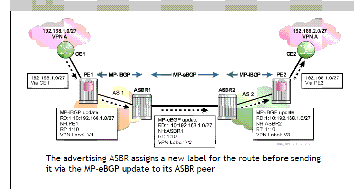
In this case mp-ebgp is used to transport vpn-ipv4 routes between the autonomous system

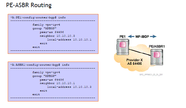
The PE and the ASBR are connected to each other using MP-IBGP the PE and the ASBR's are connected directly or are connected with the help if RR


The primary difference between MP-ibgp and mp-ebgp is the next hop attribute is changed when there is an ebgp session then when there is an mp-ibgp session

The LSP path terminates on the ASBR originating the update.

The ASBR has to assign a new label for the route before sending it via the mp-ebgp peer ie to its peer ASBR

See the figure for the detailed description of the routes being generated from one CE to another CE

Configuration for Model B:-

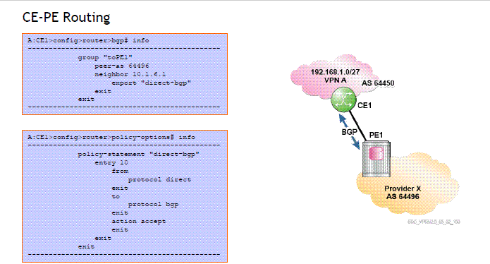
1> CE-PE routing:-


2> VPRN configuration on the PE:-


Configuration of MP-ibgp between the PE and the ASBR:-


For MP-EBGP between the two AS's use the command enable-inter-as-vpn


Verification:-

CE-PE routing verification:-

show router bgp summary

PE-ASBR routing verification

Show router bgp summary

ASBR-ASBR routing verification:-

show router bgp summary

CE routing table:-

show router route-table

PE route table verification:-

show router 10 route-table

As seen below when the route is advertised from ASBR2 to PE2 the next hop is modified as the next hop is modified the vpn label is modified as well. This is also true in the case when the labels are advertised between the ASBR's as well.


BGP inter AS label can be viewed by using the following command:-


Monday, February 20, 2012

Inter AS VPRN--Model A


This is used to interconnect vprn of customers connected to different service providers


There are 3 models the first model is known as VRF to VRF approach


Here the ASBR 's from two different AS's are connected directly


For each VPRN services there is a requirement of different logical or physical interfaces


ASBR of AS serves as a PE as well as a CE


EBGP is used to distribute routes to its peers


The above figure describes what happens in the control plane, 

1> CE1 advertises the routes 192.168.1.0/27 to PE1

2> PE1 adds a vpn label and transmits the route to PE/ASBR1

3> The vpn label is stripped of in ASBR1 and a ipv4 route update is sent to Pe2/asbr2

4> ASBR2 treats ASBR1 as a CE device and after it receives the update adds a vpn label v2 and sends the route to PE2

5> PE2 puts that under the appropriate service and transfers it to the CE


Configuration between PE and CE:-

1> Routing between CE and PE


2> VPRN configuration in PE:-


3> Verify that the BGP is in established state:-

show router bgp neighbor on the CE

4> Configure MPBGP between the PE1 and the ASBR


5> Show router bgp neighbor on PE will verify it is established with the CE router

6> Export policy mpbgp to bgp will redistribute the mpbgp routes to the bgp policy is given above.


7> show router 10 route table on the PE's shows us the route which have been distributed 


8> On CE devices use the command show router route table

9> 

EBGP is used to distribute the routes no requirement of MPLS between the two ASBR

Not Scalable per vprn configuration is required on every ASBR ie ASBR needs to be configured with each and every vprn services.


Friday, February 17, 2012

DIS in ISIS

In a broadcast network a DIS is formed which in turn elects a pseudonode
All the routers exchanges information with the pseudonode
There are seperate DIS elected for both L1 and L2 updates the election of DIS is premptive the one with the highest priority wins if the priorities are equal the one with the highest mac address wins
DIS creates the pseudonode, it creates and updates the pseudonode
Conduct flooding over the lan
A priority of 0 does not mean the router is ineligible for becoming the DIS


In the above slide the router with the lowest mac address is elected as DIS as they have the same priority.

CSNP is sent every 10 seconds

If a CSNP is received which advertises a newer LSP, a PSNP request is sent requesting for the new LSP

If a newer lsp is received it is updated in the database and it is then flooded to other isis nodes

If the sequence number is same the LSP is ignored

If the sequence number is older athen what is locally present an updated LSP is sent.


The last point in the above figure suggests that the CSNP acts as an implicit acknowledgement


Friday, May 27, 2011

L3 VPN with static routes

Configuration for CE:-
===================

Default static route to the PE

#--------------------------------------------------
echo "Static Route Configuration"
#--------------------------------------------------
        static-route 0.0.0.0/0 next-hop 192.168.1.2
#--------------------------------------------------


Configurations at the PE


*A:SAS-X>config>router>bgp# info
----------------------------------------------
            family vpn-ipv4
            router-id 11.11.11.11
            group "mpbgp"
                local-address 11.11.11.11 << --- Local router id
                neighbor 10.10.10.10 <<--- Neighbor router id
                    local-address 11.11.11.11
                    local-as 1
                    peer-as 1
                exit
            exit
----------------------------------------------
*A:SAS-X>config>router>bgp#


*A:SAS-X>config>service>vprn# info
----------------------------------------------
            router-id 11.11.11.11
            maximum-routes 32000
            autonomous-system 1
            route-distinguisher 1:1010
            auto-bind ldp
            vrf-target target:1:1010
            interface "ce1" create
                address 192.168.1.2/24
                sap 1/1/14 create
                exit
            exit
            static-route 66.1.1.1/32 next-hop 192.168.1.1  <<---Static route pointing towards the CE router
            no shutdown
----------------------------------------------
*A:SAS-X>config>service>vprn#

*A:SAS-X>config>service>vprn# show router 1010 route-table

===============================================================================
Route Table (Service: 1010)
===============================================================================
Dest Prefix                                   Type    Proto    Age         Pref
       Next Hop[Interface Name]                                     Metric    
-------------------------------------------------------------------------------
66.1.1.1/32                                   Remote  Static   00h47m12s   5   <<-- CE attached
       192.168.1.1                                                  1
88.1.1.1/32                                   Remote  BGP VPN  00h22m13s   170 <<--Route from remote CE
       10.10.10.10                                                  0
172.1.1.0/24                                  Remote  BGP VPN  00h23m12s   170 <<-- Remote prefix for the AC.
       10.10.10.10                                                  0
192.168.1.0/24                                Local   Local    00h47m12s   0  
       ce1                                                          0
-------------------------------------------------------------------------------
No. of Routes: 4
===============================================================================
*A:SAS-X>config>service>vprn#

show router bgp routes vpn-ipv4

===============================================================================
 BGP Router ID:11.11.11.11      AS:1           Local AS:1         
===============================================================================
 Legend -
 Status codes  : u - used, s - suppressed, h - history, d - decayed, * - valid
 Origin codes  : i - IGP, e - EGP, ? - incomplete, > - best

===============================================================================
BGP VPN-IPv4 Routes

*A:SAS-X>config>service>vprn# show router bgp routes vpn-ipv4
===============================================================================
 BGP Router ID:11.11.11.11      AS:1           Local AS:1         
===============================================================================
 Legend -
 Status codes  : u - used, s - suppressed, h - history, d - decayed, * - valid
 Origin codes  : i - IGP, e - EGP, ? - incomplete, > - best

===============================================================================
BGP VPN-IPv4 Routes
===============================================================================
Flag  Network                                            LocalPref   MED      
      Nexthop                                                        VPNLabel 
      As-Path                                                                 
-------------------------------------------------------------------------------
u*>i  1:1010:88.1.1.1/32                                 100         None     
      10.10.10.10                                                    131069   
      No As-Path                                                              
u*>i  1:1010:172.1.1.0/24                                100         None     
      10.10.10.10                                                    131069   
      No As-Path                                                              
-------------------------------------------------------------------------------
Routes : 2
Press any key to continue (Q to quit)

Pinging between the CE routers does not require any extra configuration however the following configuration is required while pinging from the PE devices:-

*A:SAS-X# ping 172.1.1.2 router 1010

198 2011/05/19 04:42:40.66 UTC WARNING: SYSTEM #2007 Base OAM
"Test name "CliIcmpPing-6", owner name "TiMOS CLI" managed object created"
PING 172.1.1.2 56 data bytes
64 bytes from 172.1.1.2: icmp_seq=1 ttl=63 time=15.9ms.
64 bytes from 172.1.1.2: icmp_seq=2 ttl=63 time=11.0ms.
64 bytes from 172.1.1.2: icmp_seq=3 ttl=63 time=11.0ms.
64 bytes from 172.1.1.2: icmp_seq=4 ttl=63 time=10.5ms.
64 bytes from 172.1.1.2: icmp_seq=5 ttl=63 time=36.2ms.

---- 172.1.1.2 PING Statistics ----
5 packets transmitted, 5 packets received, 0.00% packet loss
round-trip min = 10.5ms, avg = 16.9ms, max = 36.2ms, stddev = 9.81ms

199 2011/05/19 04:42:44.73 UTC WARNING: SYSTEM #2008 Base OAM
"Test name "CliIcmpPing-6", owner name "TiMOS CLI" managed object deleted"
*A:SAS-X#