There are 3 models the first model is known as VRF to VRF approach
Here the ASBR 's from two different AS's are connected directly
For each VPRN services there is a requirement of different logical or physical interfaces
ASBR of AS serves as a PE as well as a CE
EBGP is used to distribute routes to its peers
The above figure describes what happens in the control plane,
1> CE1 advertises the routes 192.168.1.0/27 to PE1
2> PE1 adds a vpn label and transmits the route to PE/ASBR1
3> The vpn label is stripped of in ASBR1 and a ipv4 route update is sent to Pe2/asbr2
4> ASBR2 treats ASBR1 as a CE device and after it receives the update adds a vpn label v2 and sends the route to PE2
5> PE2 puts that under the appropriate service and transfers it to the CE
Configuration between PE and CE:-
1> Routing between CE and PE
2> VPRN configuration in PE:-
3> Verify that the BGP is in established state:-
show router bgp neighbor on the CE
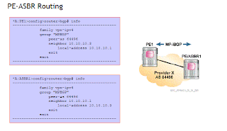
4> Configure MPBGP between the PE1 and the ASBR
5> Show router bgp neighbor on PE will verify it is established with the CE router
6> Export policy mpbgp to bgp will redistribute the mpbgp routes to the bgp policy is given above.
7> show router 10 route table on the PE's shows us the route which have been distributed
8> On CE devices use the command show router route table
9>
EBGP is used to distribute the routes no requirement of MPLS between the two ASBR
Not Scalable per vprn configuration is required on every ASBR ie ASBR needs to be configured with each and every vprn services.


No comments:
Post a Comment